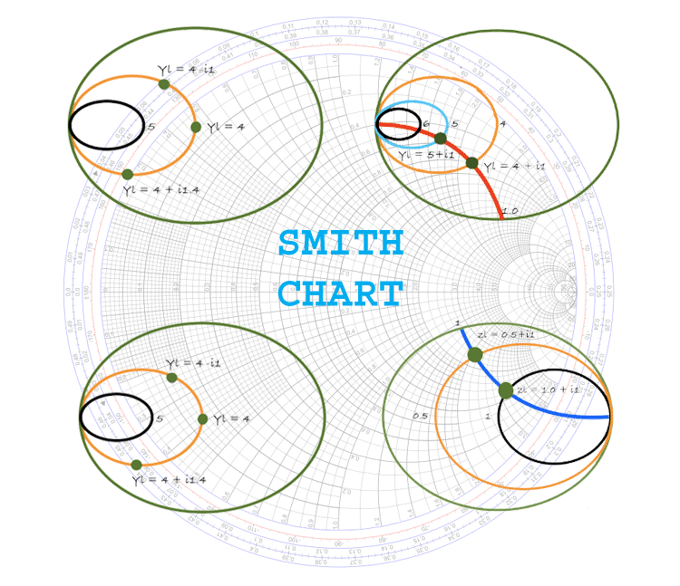

(If a particular value of Z 0 is employed widely or exclusively, it becomes worthwhile to construct a chart for that, particular value of Z 0. This avoids the need to have Smith charts for every imaginable value of line characteristic impedance. Close examination of the chart axes shows the chart has been drawn for use with normalized impedance and admittance. The greatest advantage of the Smith Chart for Transmission Line is that travel along a lossless line corresponds to movement along a correctly drawn constant SWR circle. It would be of use only if it had been decided always to use values of SWR less than 1. This SWR is thus equal to the value of r ± j0 at that point the intersection to the left of the chart center corresponds to 1/r.

Thus, when a particular circle has been drawn on a Smith chart, the SWR corresponding to it may be read off the chart at the point at which the drawn circle intersects the only straight line on the chart, on the right of the chart center. If a load is purely resistive, R/Z 0 not only represents its normalized resistance but also corresponds to the standing-wave ratio, as shown in Equation (7-8). In the quite rare case of lossy RF lines, an inward spiral must be drawn instead of the circle, with the aid of the scales shown in Figure 7-12 below the chart. The various circles and coordinates have been chosen so that conditions on a line with a given load (i.e., constant SWR) correspond to a circle drawn on the chart with its center at the center of the chart. This means that tangents drawn to the circles at the point of intersection would be mutually perpendicular. A careful look at the way in Which the circles intersect shows them to be orthogonal. The arcs of circles, to either side of the straight line, similarly correspond to various values of normalized line reactance jx = jX/Z 0. The complete circles, whose centers lie on the only straight line on the chart, correspond to various values of normalized resistance (r = R/Z 0) along the line. It consists of two sets of circles, or arcs of circles, which are so arranged that various important quantities connected with mismatched transmission lines may be plotted and evaluated fairly easily. Fundamentals of the Smith Chart:ĭescription The polar impedance diagram, or Smith Chart for Transmission Line as it is more commonly known, is illustrated in Figure 7-12. The most widely used calculator of this type is the Smith Chart for Transmission Line. The most useful representations are those that give the impedance relations along a lossless line for different load conditions. The various properties of transmission lines may be represented graphically on any of a large number of charts.


 0 kommentar(er)
